Figure 1: Simple Circuit Device
In electrical circuits, resistance is denoted R and is defined to be the slope of the voltage-versus-current curve, whenever that is well-defined. In symbols,
| R := |
| ⎪ ⎪ ⎪ ⎪ |
| (1) |
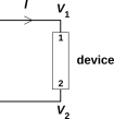
where G.C. stands for Given Conditions, which is horribly open to interpretation, as discussed below. For a device such as shown in figure 1, ΔV is the voltage drop across the device in some chosen direction. In this case, we have chosen ΔV := V1 − V2. Similarly, I is the current through the device in the same direction, namely the “1→device→2” direction, as indicated by the arrowhead next to the I symbol in the diagram. For more about the structure and interpretation of circuit diagrams, see section 2.
The unit of resistance is the ohm, defined to be one volt per amp.
Under a wide range of practical conditions, metallic wires and some other circuit elements exhibit a voltage drop ΔV proportional to the current I, in which case equation 1 simplifies to:
| R = |
| (2) |
which is called Ohm’s law. Both sides of this equation have an implicit dependence on the Given Conditions, as will be discussed below.
Whenever voltage drop across some circuit element is simply proportional to current, the element is called ohmic.
Some objects (e.g. the resistors you buy from the electronics shop) are ohmic over a wide range of Conditions, in which case it is convenient to speak of “the” resistance of the object.
Ohm’s law is absolutely not a law of nature. It can be used to describe an ohmic material after you know it is ohmic.
The ratio in equation 2 is usually much less useful than the derivative in equation 1, except for ohmic materials in which case the two are identical. Some people call the quantity in equation 2 the resistance, but this is not recommended. Normally the term resistance is reserved for the quantity in equation 1. You can call it the small-signal resistance if you want to remove the last vestige of ambiguity.
Don’t assume everything is ohmic. Nonmetals are (mostly) insulators or semiconductors, with spectacularly non-ohmic behavior. The prototypical non-ohmic device is the semiconductor diode. Ideally its current is an exponential function of voltage, which makes its resistance inversely proportional to the current.
Things get much messier when we start asking what is meant by Given Conditions in equation 1. Ideally the voltage at time t would depend on the current at time t and nothing else, but in the real world it depends on history and on other things such as temperature.
A familiar example is an incandescent light bulb. One way of understanding it is to consider the voltage drop to be a function of temperature as well as current:
| ΔV = ΔV(I, T) (3) |
Then you might choose the Given Conditions to mean constant temperature. Under these Conditions, the bulb is ohmic. These Conditions are hard to arrange, but you could do it using feedback loops and/or deft timing.
On the other hand, you could choose the Given Conditions to be normal light-bulb operation, where the bulb is surrounded by normal ambient air. In this case the temperature depends on the current, so on a longish timescale you could write
| ΔV = ΔV(I, T(I)) (4) |
and if you differentiate that w.r.t. current, you see why the device is definitely non-ohmic under these Conditions.
If you look on a faster timescale, you will find that the temperature depends on the recent history of the current, so if you try to write the voltage drop as a function of current it’s not even a function. You can still define the instantaneous resistance according to equation 1, but clearly there will be no such thing as “the” resistance of the object.
Other possible complications include:
It is a good practice to draw the circuit diagram and label it, so as to define the variables of interest. In the ultra-simple circuit shown in figure 1, the assignment of variables is conventional and might almost go without saying ... but in circuits even slightly more complicated than this, the diagram is well-nigh indispensable.
It’s ironic: experts don’t hesitate to draw the diagram, whereas naïve students – who have the most to gain from the diagram – sometimes try to get by without the diagram.
To label the voltage of a node in the diagram, it suffices to put a symbol next to the node, such as the V1 and V2 symbols in figure 1.
To label the current in a wire, we have to be slightly more careful. It is necessary to put an arrowhead on the wire. The meaning of the I symbol in figure 1 would be unclear without the arrowhead.
The arrowhead does not mean that the physical current flows the direction of the arrowhead! To understand why not, and to understand what the arrowhead does mean, the easiest approach is as follows: We define a vector current I which represents the real physical current. The scalar current I is defined to be the component of I in the direction of the arrowhead. That is, the arrowhead serves as a basis vector.
| If the arrowhead points rightward and I is positive, the physical current I is flowing rightward. | If the arrowhead points rightward and I is negative, the physical current I is flowing leftward. |
| If the arrowhead points leftward and I is positive, the physical current I is flowing leftward. | If the arrowhead points leftward and I is negative, the physical current I is flowing rightward. |
Let’s be clear:
The direct physical significance of the vector current includes:
Note: The law of conservation of charge (aka Kirchhoff’s junction rule) can be expressed by adding the scalar currents with due regard to signs. This conservation law can also be expressed in terms of the vector currents, but not just by adding the current vectors. If you want to know how to do it right, see reference 1 ... but for ordinary circuits you should just use the scalar currents for expressing the conservation law. In fact, applying the addition-of-vectors formula to the current vectors in two different wires is almost never useful. The main reason for mentioning the vector current is to explain the significance of the arrowhead(s) in the circuit diagram.