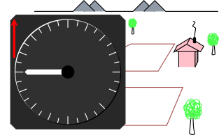
Figure 1: Standard Aircraft Accelerometer: Upright
An ordinary accelerometer sitting upright on the shelf reads +1 g (not zero). If you turn it upside down, it reads −1 g. This is as it should be, even though the accelerometer is not being accelerated relative to the lab frame. This may come as a surprise to some folks, because in high school physics it is customary to measure everything relative to the lab frame. However, according to modern (post-1915) physics, there are many situations where you might wish to measure acceleration relative to a nearby freely-falling frame.
By way of background: Galileo’s principle of relativity tells us that there is no such thing as absolute velocity. Velocity is always relative. It is relative to some chosen reference frame.
In contrast: The same is not true of acceleration. There definitely is a notion of absolute acceleration. You are allowed to measure acceleration relative to any frame you like, but not all frames are equivalent. It is more natural to measure absolute acceleration, which is (by definition) relative to a local freely-falling reference frame. (The velocity of the frame and other details do not matter, so long as the frame is freely falling and reasonably nearby.)
Ordinary standard accelerometers measure absolute acceleration. This means that they register +1g when at rest, upright, in the lab frame. They definitely do not measure acceleration relative to the lab frame. Relative to any freely falling reference frame, the entire lab is being accelerated skywards at a rate of +1g, as discussed in reference 1.
Accelerometers are sometimes installed in aircraft, especially aerobatic aircraft and combat aircraft. In straight-and-level upright flight, the accelerometer reads +1g, as shown in figure 1.
Do not be fooled by the fact that the needle is horizontal. It is pointing to +1, not 0.
Acceleration is a vector. The instrument measures one component of this vector, namely the projection onto the direction indicated by the red arrow shown in the figure.
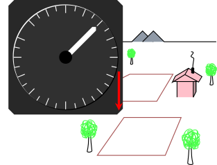
We can obtain another data point by flying inverted. In straight-and-level inverted flight, the accelerometer reads −1g. Figure 2 show how this looks from the lab-frame point of view. The meter reads −1g.
This is also how the accelerometer looks if it is just sitting on the laboratory shelf, upside down. To repeat: the meter reads −1g.
|
| |
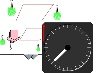
| Figure 2: Standard Aircraft Accelerometer: Inverted, Lab View | Figure 3: Standard Aircraft Accelerometer: Inverted, Pilot’s View | |
Meanwhile, figure 3 shows how things look from the pilot’s point of view, in inverted flight. The pilot is upside down, along with the accelerometer and the rest of the airplane. This is the same as figure 2, but the whole picture has been rotated.
It is possible to make an accelerometer in about 20 minutes, using a lead weight, two rubber bands, a dowel rod, and some baling wire. Coat hanger wire will do, if you don’t have a supply of baling wire on hand.
The dowel rod is 24 inches long and 0.5 inches in diameter.
First, make a “carrier” as shown in the middle of the diagram. It is made of a single piece of baling wire. The carrier wire has a straight portion about 4 inches long in this example; adjust this to fit the length of your weight. The straight portion segues into loop at each end. Each loop slides freely on the rod. During construction, twist the loop a couple of times to provide structural strength, in accordance with time-honored baling-wire construction principles. Use the very last bit of length at each end, as it emerges from the twist, to make pegs to which the lead weight attaches.
Note the spelling: baling wire not “bailing wire”.
For the weight, I used a 3 ounce piece of lead that had fallen off somebody’s tire. I picked it up from the roadside, and straightened it using an anvil and a small hammer. I drilled small holes to receive the pegs.
In the figure, I pulled the weight off one of the pegs, so you can see the straight section of the carrier wire. Normally the weight would be flush against the straight wire.
Near each end of the stick, install a loop of baling wire, twisted tight so it doesn’t slide, to serve as a retainer for the rubber band.
Cut open each rubber band to make a single filament, rather than a loop. Attach one end to the carrier using two half hitches. Attached the other end to the retainer near the end of the stick; you can use half hitches, or just pinch it between the wire and the wood.
Using flimsier rubber bands and/or a heavier weight will maximize the sensitivity of the instrument.
The instrument measures the projection of g along its length. When horizontal, as shown in the figure, it reads zero. If you hold it with the “top” end up, it reads +1. If you hold it the other way up, it reads -1.
Select one of the loops on the carrier to use as a pointer, and mark the stick with appropriate readings. (My markings are not visible in figure 4.)
For starters, just play with the instrument. Hold it horizontal, and wiggle it back and forth along its length, to convince yourself that it really does measure acceleration. Then hold it vertically right-side-up, then turn it upside-down. Dandle it up and down.
You can also attach a string and swing the instrument around and around to create a centrifugal field. Observe the angle of the string, and the corresponding accelerometer reading: a 45 degree angle should correspond to 1.41 Gees, and a 60 degree angle should correspond to 2 Gees. Here we are treating the centrifugal field on the same basis as the gravitational field, as we should. Both show up as an acceleration, in accordance with Einstein’s equivalence principle.
To use the instrument to measure the weightlessness of free fall, hold it high with one hand, drop it, and catch it with the other hand. Catch it so that you clutch the weight and the stick together, so as to preserve the free-fall reading, which you can then examine at leisure.
Another design for a home-made accelerometer can be found in reference 2. For more about the gravitational field and how we perceive it reference 1. For more about the definition of weight and weightlessness, and about what’s relative and what’s not, see reference 3.
